
RF-19 SENSE2CAN Sensor Modules
Summary
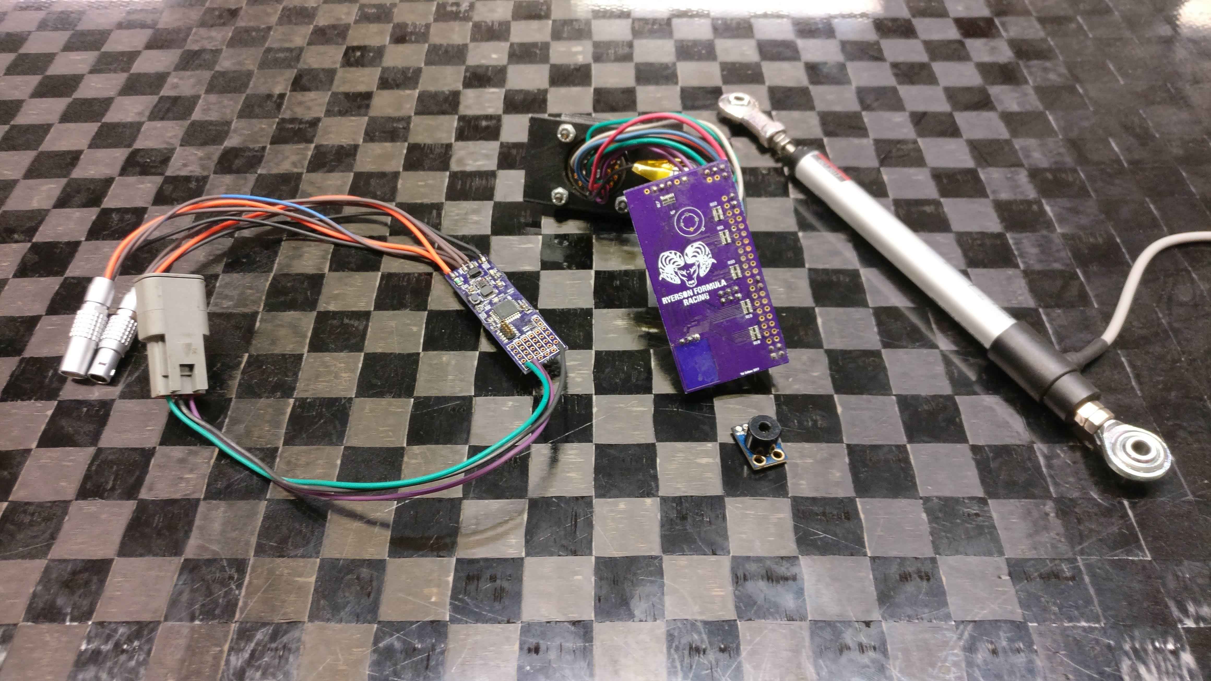
The SENSE2CAN module (S2C for short) is a CAN bus data acquisition module for Ryerson Formula Racing's RF-19 vehicle. The modules were designed to be slim, cheap, and versatile.
Backstory
The S2C modules were meant to be an upgrade from the RF-17 sensor modules that I developed in 2017 for the team. The RF-17 modules did the job in terms of expanding the I/O capabilities of the ECU over CAN bus and reducing overall wire length on the car. However, due to their “hub” design philosophy, each of the 5 modules had all nearby sensors connected to them. This required a high pin-count connector which was harder to work with, and it meant that if any of the modules went offline (due to maintenance or failure), a large amount of sensor data would be lost. The fast pace of the FSAE design-test-compete cycle meant that sensors were fitted on the car progressively. Each new sensor addition meant that the module and its connected harness would have to be taken apart and reworked. This created a large barrier of entry for each new sensor; not something you want when you have 100s of other things to do on the car. This was one of the major issues that the S2C modules solved.
Here you can see the size difference beween the RF-19 module (left) and the older RF-17 module (right):
Objectives
Based on the flaws of the RF-17 modules, the S2C modules were designed with the following goals in mind:
- Be as slim and as cheap as possible so that many modules can be inlined with the harness; potentially even one module per sensor
- Simplify firmware development by providing a way to differentiate the boards on the hardware level, so that the same firmware image could be reused for all modules
- Provide easy-to-use breakouts for the most common sensor interfaces (analog and I2C), while keeping the board flexible for other future uses
Features
The SENSE2CAN has the following features:
- ATSAMC21E18A 32-bit ARM Cortex M0+ MCU
- CAN bus connectivity with ESD protection and optional on-board termination
- 4 dedicated analog inputs
- Dedicated I2C breakout
- Breakout area for all I/O pins
- +5V and GND breakout
- 4 pinstraps meant for configuring CAN ID through the BOM to avoid firmware modification
- Power status LED
- Generic GPIO-controlled LED
- 8-26V input with transient suppression, reverse polarity protection and PTC fuse
Pinstraps
One major advantage of the S2C modules is that for the common sensors, all modules can use the same exact firmware. This is possible because each of the four wheels has the same sensor configuration. That means that the only difference between the four wheel modules is the ID of the CAN messages that it sends back to the ECU. This is why the modules include 4 pinstraps for setting their ID on the hardware level. A pinstrap in this case is a combined footprint of a pull-up and pull-down resistor of a dedicated digital input. Since the footprints are combined, a resistor can be either in the pull-up or pull-down configuration; a 1 or a 0. At startup, all 4 pinstrap inputs are read, and their values are used to determine the board's ID. Given that there are 4 of them, the ID is a 4-bit value, meaning 16 possible unique IDs. In the code, the board ID is then used to differentiate what the board type is (meaning which sensors are connected to it), and what CAN ID address space to use. Each ID has 16 CAN IDs that it can use. The different board types and their configurations can be seen in the following code excerpt from s2c_utils.h:
enum s2c_board_type {
	/* S2C board mounted near wheels:
	 * - 1 analog input:
	 * --> suspension potentiometer
	 * - 1 I2C slave:
	 * --> brake temperature sensor
	 *
	 * CAN setup:
	 * - frame 1: 4 bytes
	 * --> bytes 0 & 1: suspension potentiometer
	 * --> bytes 2 & 3: brake temperature
	 */
	S2C_BOARD_WHEEL,
	/* S2C board used for tire temperature bar:
	 * - 3 I2C slaves:
	 * --> outer tire temp
	 * --> middle tire temp
	 * --> inner tire temp
	 *
	 * CAN setup:
	 * - frame 1: 6 bytes
	 * --> bytes 0 & 1: outer tire temp
	 * --> bytes 2 & 3: middle tire temp
	 * --> bytes 4 & 5: inner tire temp
	 */
	S2C_BOARD_TIRE_TEMP,
	/* S2C board mounted near radiator:
	 * - 2 analog inputs:
	 * --> radiator inlet temperature
	 * --> radiator outlet temperature
	 *
	 * CAN setup:
	 * - frame 1: 4 bytes
	 * --> bytes 0 & 1: radiator inlet temperature
	 * --> bytes 2 & 3: radiator outlet temperature
	 */
	S2C_BOARD_RADIATOR,
	/* Any other S2C board use */
	S2C_BOARD_OTHER
};
And the physical layout is also described in the same file:
/*
 * Returns board type based on the board ID.
 * ID = 0 to 3: S2C_BOARD_WHEEL
 * ID = 4 to 7: S2C_BOARD_TIRE_TEMP
 * ID = 8:		S2C_BOARD_RADIATOR
 * All others:	S2C_BOARD_OTHER
 *
 * Order follows CAN bus order:
 *           __
 *          /  \
 *   2,6 FL ---- FR 3,7
 *         / CM  <------- CENTRAL MODULE
 *        |      |
 *        |      | RAD 8
 *         \    /
 *  1,5 RL |----| RR 0,4
 *         |____|
 *
 */
Flywire fixes
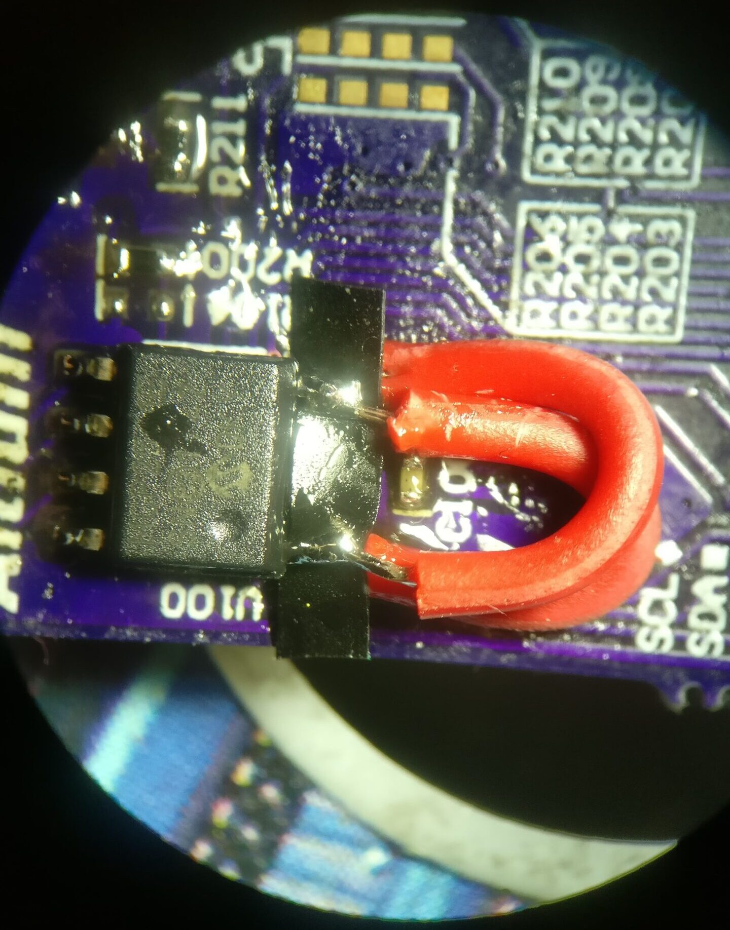
During initial board bringup, CAN bus communication wasn't working. After going through the basic troubleshooting steps with no luck (including making sure that the CAN transceiver is not in standby mode), I dived into the schematics to carefully examine them. After banging my head against the wall enough times, I discovered that I swapped the CAN Tx and Rx lines! It was my first time using Altium Harnesses, and somehow I must've gotten the two pins mixed up.
The solution was pretty straightforward in theory, but tricky to successfully implement: lift the Tx/Rx pins on the transceiver, and solder flywires from the lifted pins to their respective pads. This is what it looked like:
Gallery

Layout

3D render

3D render
Assembled board